
This tutorial will show you how to upgrade your wiring harness. The purpose for this upgrade is to improve the output of the factory lighting while retaining DRLs (daytime running lights).
Before I start, credit is due to sciphi for coming up with this idea. He was the first to do this (albeit differently and more expensively than I did), and his implementation is proper and his results are excellent. If you like this thread, do drop him a line and thank him for his contribution.
https://www.cruzetalk.com/forum/11-...orum/11-appearance-body/4284-better-lighting-old-school-way-harnesses-more.html
Why should I upgrade my wiring harness?
The factory wiring harness is downright disappointing and comes in at around 20-22 gauge wiring. By comparison, even a 95 GM w-body has 16 gauge wiring. The understanding is that this was done to preserve headlight life but at the expense of output. Upgrading your harness significantly improves output as well as visibility.
This is 100% legal and will not void any part of your warranty. This can be reversed at any time with absolutely no traces and is considered an upgrade for all intents and purposes.
How does this upgrade work?
The upgraded wiring harness uses a thicker wire. It taps directly into the driver side headlight socket. The upgraded wiring harness connects directly to your car's power distribution center with much thicker wiring (14 or 16 gauge, I didn't measure to be exact) and reduces voltage drop in order to provide an optimal power source for your headlight bulbs. The harness uses the factory wiring's headlight bulb socket as an on-off switch for a pair of relays that enable and disable the flow of power through the upgraded wiring harness.
Is it safe?
This wiring harness is thoroughly insulated and is rated for up to 100W per bulb and is heat proof to 480 degrees Fahrenheit. It is perfectly safe.
What do I need?
Parts needed:
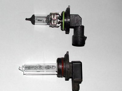
To start, the wiring harness. This is a Putco model 239008HW wiring harness. .
Putco 239008HW Premium Automotive Lighting H13/9008 100W Heavy Duty Wiring Harness and Relay
A capacitor, either polar or non-polar, axial or radial. Electrolytic is fine. You can find this at your nearby radio shack or on mouser.com. Sciphi used a 470uF Polar and I used a 330UF 100V NPE capacitor with equal success. Both of our capacitors were axial capacitors. They are however overkill, and a smaller capacitor can be used.
Zipties, for making this a neat install and keeping the wiring out of places where it could get snagged or burned. I used 14 zipties. Anything from 4" to 8" will be fine.
Electrical tape.
Butt-end connectors good for 14AWG wire.
Tools needed:
Wire cutter & stripper
Strong pliers or crimp tool (if using butt-end connectors)
10mm and 13mm sockets or wrenches
A soldering iron and some electrical solder
How do I install it?
If you need additional instructions or pictures, feel free to ask.
1. To start, spread out the wiring harness so you can see all of the ends. Connect the relays to their respective connectors. You will end up with the following "nodes:"
One male H13 bulb connector
Two female H13 bulb connectors
Two ground wires with crimped o-ring terminals
Two power wires with crimped o-ring terminals
Two relays
2. The two power wires with crimped o-ring terminals will be connected to the power distribution center. This is directly on top of the battery on the passenger side of the car and has a lid. You will see a red battery wire going directly into it. Open this lid and connect the two power wires that are together to the terminal shown here. You will need the 13mm socket to remove this nut. Tighten until its secure, but do not over-tighten this; its not an axle nut. Your end result should look like this:
![Image]()
3. Run the wire alongside the battery:
![Image]()
4. Remove the washer fluid tube. This will lift right out and will give you more space to work with.
5. Disconnect the headlight connectors by pulling back on the grey tab and pushing down on the eject lock while pulling out on the connector.
6. Looking at the wiring harness, you will now see some color-coded wires. From the male H13 bulb connector will be a white, black, and red wire. Cut the white wire about halfway between the shield sleeve and the socket itself. Strip 1/4" of jacket off of each end of each wire.
7. From the relay pair will come two yellow wires; one of which will go to the female socket on the driver side, and the other to the female socket on the passenger side (the longer length of wire). Cut the yellow wire that's on the driver's side about half way between the socket and the shield sleeve. Strip 1/4" of jacket off of each end of each wire.
9. You will now have two ends of yellow wire and two ends of white wire. The next step is to solder the ends of your capacitor from one of the yellow wires to one of the white wires. It doesn't matter which wire. If you have a non-polar axial capacitor, it won't matter how it is oriented. If you have a polarized axial capacitor, solder the anode (end with the arrows facing away from it) to the white wire. Solder the cathode to the yellow wire. Here's how you can tell:
![Image]()
Once you're done, it should look like this. I used this capacitor because it was lying around. You could use a 16V capacitor instead of the 100V I used.
![Image]()
10. Next, use the butt-end connectors to re-connect the wires you cut. Essentially, yellow (with capacitor end soldered) connected to yellow, white (with capacitor end soldered) connected to white. Wrap it all up in electrical tape. Should look like this when its done:
![Image]()
11. Ziptie the relays so they don't bounce around:
![Image]()
12. Connect the ground wire coming out of the driver's side female bulb connector to the chassis. You'll need the 10mm socket/wrench here. I'd suggest using this anchor, which is directly above the corner of the radiator:
![Image]()
13. Remove the air filter box. Instructions can be found here:
https://www.cruzetalk.com/forum/57-how-forum/5479-how-bypass-intake-resonator.html
14. Connect the H13 female connectors to the bulbs.
15. Run the wire cleanly alongside the existing wire above the fan shroud and ziptie it in place, but do not tighten the zipties. Leave them loose so you can move the wiring harness around before you tighten it in place. I put an arrow next to each ziptie location I used, but you don't have to put them in that exact place; these pictures are just used to give you an idea of what it should look like and how close the zipties should be to each other. Once you have the wiring in the position you need it, tighten the zipties, but do not over-tighten them. This way, you'll be able to cut them in case you decide to remove the harness in the future.
![Image]()
![Image]()
16. Connect the ground wire coming out of the passenger's side bulb connector to the chassis. You'll need to use the 10mm socket/wrench here:
![Image]()
17. Ziptie the remaining wires together so it doesn't stick out anywhere
![Image]()
18. Put the washer fluid tube back in its place
19. Test the headlights for both DRL, low beam, and high beam function. Keep in mind. DRLs will not turn on if the hand brake is pulled. If you hear a buzzing noise when testing the DRLs and the bulbs don't light up, come back and post in this thread; you didn't wire the capacitor correctly. You'll need to release the handbrake first. You can manually turn the headlights on using the switch to the left of the steering wheel. If you hear a
Once you're done, the wires on both sides should be nicely zip tied and the wires on the driver side tucked behind the headlight assembly. Don't force the wires with the capacitor connected into a place they won't fit or you could break the leads off of the capacitor.
Enjoy your upgraded lighting. As a side note, Sylvania's XtraVision bulbs are highly recommended as a complement to this upgrade.
EDIT: There is a need for an inline fuse for both power wires going to the battery. I will be adding one some time this week and will update this writeup to include instructions for it.
Before I start, credit is due to sciphi for coming up with this idea. He was the first to do this (albeit differently and more expensively than I did), and his implementation is proper and his results are excellent. If you like this thread, do drop him a line and thank him for his contribution.
https://www.cruzetalk.com/forum/11-...orum/11-appearance-body/4284-better-lighting-old-school-way-harnesses-more.html
Why should I upgrade my wiring harness?
The factory wiring harness is downright disappointing and comes in at around 20-22 gauge wiring. By comparison, even a 95 GM w-body has 16 gauge wiring. The understanding is that this was done to preserve headlight life but at the expense of output. Upgrading your harness significantly improves output as well as visibility.
This is 100% legal and will not void any part of your warranty. This can be reversed at any time with absolutely no traces and is considered an upgrade for all intents and purposes.
How does this upgrade work?
The upgraded wiring harness uses a thicker wire. It taps directly into the driver side headlight socket. The upgraded wiring harness connects directly to your car's power distribution center with much thicker wiring (14 or 16 gauge, I didn't measure to be exact) and reduces voltage drop in order to provide an optimal power source for your headlight bulbs. The harness uses the factory wiring's headlight bulb socket as an on-off switch for a pair of relays that enable and disable the flow of power through the upgraded wiring harness.
Is it safe?
This wiring harness is thoroughly insulated and is rated for up to 100W per bulb and is heat proof to 480 degrees Fahrenheit. It is perfectly safe.
What do I need?
Parts needed:
To start, the wiring harness. This is a Putco model 239008HW wiring harness. .
Putco 239008HW Premium Automotive Lighting H13/9008 100W Heavy Duty Wiring Harness and Relay
A capacitor, either polar or non-polar, axial or radial. Electrolytic is fine. You can find this at your nearby radio shack or on mouser.com. Sciphi used a 470uF Polar and I used a 330UF 100V NPE capacitor with equal success. Both of our capacitors were axial capacitors. They are however overkill, and a smaller capacitor can be used.
Zipties, for making this a neat install and keeping the wiring out of places where it could get snagged or burned. I used 14 zipties. Anything from 4" to 8" will be fine.
Electrical tape.
Butt-end connectors good for 14AWG wire.
Tools needed:
Wire cutter & stripper
Strong pliers or crimp tool (if using butt-end connectors)
10mm and 13mm sockets or wrenches
A soldering iron and some electrical solder
How do I install it?
If you need additional instructions or pictures, feel free to ask.
1. To start, spread out the wiring harness so you can see all of the ends. Connect the relays to their respective connectors. You will end up with the following "nodes:"
One male H13 bulb connector
Two female H13 bulb connectors
Two ground wires with crimped o-ring terminals
Two power wires with crimped o-ring terminals
Two relays
2. The two power wires with crimped o-ring terminals will be connected to the power distribution center. This is directly on top of the battery on the passenger side of the car and has a lid. You will see a red battery wire going directly into it. Open this lid and connect the two power wires that are together to the terminal shown here. You will need the 13mm socket to remove this nut. Tighten until its secure, but do not over-tighten this; its not an axle nut. Your end result should look like this:
3. Run the wire alongside the battery:
4. Remove the washer fluid tube. This will lift right out and will give you more space to work with.
5. Disconnect the headlight connectors by pulling back on the grey tab and pushing down on the eject lock while pulling out on the connector.
6. Looking at the wiring harness, you will now see some color-coded wires. From the male H13 bulb connector will be a white, black, and red wire. Cut the white wire about halfway between the shield sleeve and the socket itself. Strip 1/4" of jacket off of each end of each wire.
7. From the relay pair will come two yellow wires; one of which will go to the female socket on the driver side, and the other to the female socket on the passenger side (the longer length of wire). Cut the yellow wire that's on the driver's side about half way between the socket and the shield sleeve. Strip 1/4" of jacket off of each end of each wire.
9. You will now have two ends of yellow wire and two ends of white wire. The next step is to solder the ends of your capacitor from one of the yellow wires to one of the white wires. It doesn't matter which wire. If you have a non-polar axial capacitor, it won't matter how it is oriented. If you have a polarized axial capacitor, solder the anode (end with the arrows facing away from it) to the white wire. Solder the cathode to the yellow wire. Here's how you can tell:

Once you're done, it should look like this. I used this capacitor because it was lying around. You could use a 16V capacitor instead of the 100V I used.
10. Next, use the butt-end connectors to re-connect the wires you cut. Essentially, yellow (with capacitor end soldered) connected to yellow, white (with capacitor end soldered) connected to white. Wrap it all up in electrical tape. Should look like this when its done:
11. Ziptie the relays so they don't bounce around:
12. Connect the ground wire coming out of the driver's side female bulb connector to the chassis. You'll need the 10mm socket/wrench here. I'd suggest using this anchor, which is directly above the corner of the radiator:
13. Remove the air filter box. Instructions can be found here:
https://www.cruzetalk.com/forum/57-how-forum/5479-how-bypass-intake-resonator.html
14. Connect the H13 female connectors to the bulbs.
15. Run the wire cleanly alongside the existing wire above the fan shroud and ziptie it in place, but do not tighten the zipties. Leave them loose so you can move the wiring harness around before you tighten it in place. I put an arrow next to each ziptie location I used, but you don't have to put them in that exact place; these pictures are just used to give you an idea of what it should look like and how close the zipties should be to each other. Once you have the wiring in the position you need it, tighten the zipties, but do not over-tighten them. This way, you'll be able to cut them in case you decide to remove the harness in the future.
16. Connect the ground wire coming out of the passenger's side bulb connector to the chassis. You'll need to use the 10mm socket/wrench here:
17. Ziptie the remaining wires together so it doesn't stick out anywhere
18. Put the washer fluid tube back in its place
19. Test the headlights for both DRL, low beam, and high beam function. Keep in mind. DRLs will not turn on if the hand brake is pulled. If you hear a buzzing noise when testing the DRLs and the bulbs don't light up, come back and post in this thread; you didn't wire the capacitor correctly. You'll need to release the handbrake first. You can manually turn the headlights on using the switch to the left of the steering wheel. If you hear a
Once you're done, the wires on both sides should be nicely zip tied and the wires on the driver side tucked behind the headlight assembly. Don't force the wires with the capacitor connected into a place they won't fit or you could break the leads off of the capacitor.
Enjoy your upgraded lighting. As a side note, Sylvania's XtraVision bulbs are highly recommended as a complement to this upgrade.
EDIT: There is a need for an inline fuse for both power wires going to the battery. I will be adding one some time this week and will update this writeup to include instructions for it.