

Happy New Year!
This is a variation on the original mechanical solution thread which is found at-

 www.cruzetalk.com
Thanks very much to the OP for a great thread!!!
www.cruzetalk.com
Thanks very much to the OP for a great thread!!!
---------------------------------
NEW-
There is now a group of "how-to" writeups located at-
 www.cruzetalk.com
---------------------------------
www.cruzetalk.com
---------------------------------
I replaced my '12's thermostat last year because the gasket was leaking rather badly and the housing appeared to be weeping through the plastic (as revealed using UV dye in the coolant).
For that reason I did not save the OEM housing and the new one is aftermarket (and not Dorman) so I cannot easily try the mechanical core replacement as shown in the original thread.
Besides, 180F was a little low for me and I wanted something closer to 195-200F as others have expressed.
My unmodified thermostat ran at about 222-225F when cruising around normally, and reached 230F under load conditions.
This is completely insane as far as I am concerned and required attention.
Being an engineer I got to thinking, if the thermostat is electrically controlled (or at least "modified") by the ECU, why not just electrically adjust the operating temperature?
According to my FSM, page 9-596 (see below), at 0V to the internal heating element the opening temperature is 221F (105C).
And at 12V applied to the element the opening temperature is 176F (80C).
Notice that the fully open temperature is stated to be a staggering 248F (120C)...gasp!
![Image]()
The element has an electrical resistance of about 16.2 ohms, or at least mine does.
So at 12 volts it will dissipate about 8.9 watts.
My target of around 200F is roughly halfway between the FSM's stated 0 and 12 volt temperature values.
But I suspected it is non-linear for the applied voltage, being instead proportional to the power being dissipated.
My target was therefore about 4.5 watts.
For a 16.2 ohm heater element that would be at approximately 8.5 volts applied.
So I needed to drop ~3.5 volts from the switched battery voltage rail that is available on pin 1 of the E41 connector to the thermostat housing (page 9-40 of the FSM, shown below).
![Image]()
At 12 volts that would require a series resistor from the bottom end of the heater to ground of about 6.65 ohms.
![Image]()
Such a resistor would dissipate around 1.8 watts, but being in the hot engine bay it needs to be de-rated to at least double that.
I happened to have a 6.3 ohm 10 watt resistor on hand, so that was what I used.
You could use a common "anti-hyperflash" load resistor as found for LED turn signal applications.
They tend to be right at 6 ohms in resistance and 25-50 watts in capacity (overkill but so what?).
Next there was the problem of satisfying the ECU which monitors things such as this for being disconnected.
I happened to have (literally) about a thousand 2.2K ohm 1/4 watt resistors laying around, so I connected six of them in parallel to get a net resistance of around 367 ohms, replacing the thermostat heater across the E41 connector in the connections shown above.
This will keep the ECU happy so it doesn't set any fault codes and even when the ECU switches the output on fully it will only dissipate 0.4 watts (but again it must be derated for being in the engine bay).
This is my test circuit-
![Image]()
I used a 3/8" ring terminal to obtain a good engine ground from the bolt that holds an external cam sensor in place.
The switched + is available on pin 1 of the E41 connector-
![Image]()
So now the problem became how to make proper and safe electrical connections.
I do not generally like to modify the factory wiring, though you could splice into the wiring if you wish.
You cannot easily or cheaply find a replacement for the harness connector, and cannot find an equivalent of the thermostat housing end at all.
But as it turns out the connector pins are about 0.108" in width (2,8mm) which fits with the "2.8 DCS" designation shown in the FSM (see above).
So male and female terminals such as are used on the narrow pins of car speakers will work nicely (0.110" tab terminals and female disconnects).
You can find them on eBay and elsewhere pretty easily.
22-24 gauge wire is more than adequate for connections because the currents are small.
A note of caution-
When wiring the female tabs for the thermostat housing, use heat shrink tubing over them so that they cannot short together.
If they do short to each other you will either overheat the 6 ohm drop resistor, or blow the KR75 fuse, or both.
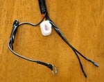
And be certain to use dielectric grease (silicone grease, or plumber's grease) on all the connections to exclude moisture because the original weather seals will not longer be present (note the goo in the connector as shown below).
This is what my setup looks like-
![Image]()
![Image]()
I 3D-printed a fancy holder for the two male tabs to the E41 connector, but it is not necessary.
---------------------------------------------------------------
Long story short (I know, too late...), it works..!
---------------------------------------------------------------
Now it runs at 194-198F at low cruising loads and at about 201-204F on the highway or when climbing hills.
So far, after dozens of warm up cycles and restarts, no DTCs, no issues of any kind, and no apparent hit to gas mileage that I have seen so far (or too small to notice).
Because the electrical system voltage at E41-1 is not really 12 volts (it varies), that may account for some of the variations I am seeing in temperature.
Next I am going to try using a regulated voltage to the thermostat heater instead.
This will have the advantage of being easily adjustable and will have a schematic like this-
![Image]()
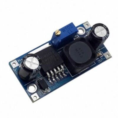
The regulator I will try is a commonly available LM2596HV 3 ampere regulator module like this-
![Image]()
These are not expensive, and you can find even cheaper ones (but be careful of the input and output capacitors, the ones as shown above are the better ones)-
Anyway, I wanted to offer this alternative method of controlling the engine thermostat temperature that takes advantage of the built-in electrical heating element.
I know that it is not for everyone, but if you are a bit electrically inclined it is a non-invasive and easy to install and de-install method.
And it definitely works...
This is a variation on the original mechanical solution thread which is found at-
1.4 ECO - Thermostat Swap - 221°F to 176°F!
OK, let’s start! I had multiple Cruze cars since 2011, unfortunately I can’t say I have/had one free of issues! Talking about the heating and cooling, I saw different & multiple issues reported by people. I did many changes to my cars during the years and I’m going to share with you a few...
---------------------------------
NEW-
There is now a group of "how-to" writeups located at-
HOW TO- Electrical control of the 1.4T (LUJ) thermostat...
Per @Blasirl here are a group of tutorial writeups and links to 3D printed part file sources. They describe methods and options for electronically controlling the thermostat temperature on 1.4T (LUJ) engines, and defeating the active "Aero" grille shutters. The effect of these modifications is...
I replaced my '12's thermostat last year because the gasket was leaking rather badly and the housing appeared to be weeping through the plastic (as revealed using UV dye in the coolant).
For that reason I did not save the OEM housing and the new one is aftermarket (and not Dorman) so I cannot easily try the mechanical core replacement as shown in the original thread.
Besides, 180F was a little low for me and I wanted something closer to 195-200F as others have expressed.
My unmodified thermostat ran at about 222-225F when cruising around normally, and reached 230F under load conditions.
This is completely insane as far as I am concerned and required attention.
Being an engineer I got to thinking, if the thermostat is electrically controlled (or at least "modified") by the ECU, why not just electrically adjust the operating temperature?
According to my FSM, page 9-596 (see below), at 0V to the internal heating element the opening temperature is 221F (105C).
And at 12V applied to the element the opening temperature is 176F (80C).
Notice that the fully open temperature is stated to be a staggering 248F (120C)...gasp!
The element has an electrical resistance of about 16.2 ohms, or at least mine does.
So at 12 volts it will dissipate about 8.9 watts.
My target of around 200F is roughly halfway between the FSM's stated 0 and 12 volt temperature values.
But I suspected it is non-linear for the applied voltage, being instead proportional to the power being dissipated.
My target was therefore about 4.5 watts.
For a 16.2 ohm heater element that would be at approximately 8.5 volts applied.
So I needed to drop ~3.5 volts from the switched battery voltage rail that is available on pin 1 of the E41 connector to the thermostat housing (page 9-40 of the FSM, shown below).
At 12 volts that would require a series resistor from the bottom end of the heater to ground of about 6.65 ohms.
Such a resistor would dissipate around 1.8 watts, but being in the hot engine bay it needs to be de-rated to at least double that.
I happened to have a 6.3 ohm 10 watt resistor on hand, so that was what I used.
You could use a common "anti-hyperflash" load resistor as found for LED turn signal applications.
They tend to be right at 6 ohms in resistance and 25-50 watts in capacity (overkill but so what?).
Next there was the problem of satisfying the ECU which monitors things such as this for being disconnected.
I happened to have (literally) about a thousand 2.2K ohm 1/4 watt resistors laying around, so I connected six of them in parallel to get a net resistance of around 367 ohms, replacing the thermostat heater across the E41 connector in the connections shown above.
This will keep the ECU happy so it doesn't set any fault codes and even when the ECU switches the output on fully it will only dissipate 0.4 watts (but again it must be derated for being in the engine bay).
This is my test circuit-
I used a 3/8" ring terminal to obtain a good engine ground from the bolt that holds an external cam sensor in place.
The switched + is available on pin 1 of the E41 connector-
So now the problem became how to make proper and safe electrical connections.
I do not generally like to modify the factory wiring, though you could splice into the wiring if you wish.
You cannot easily or cheaply find a replacement for the harness connector, and cannot find an equivalent of the thermostat housing end at all.
But as it turns out the connector pins are about 0.108" in width (2,8mm) which fits with the "2.8 DCS" designation shown in the FSM (see above).
So male and female terminals such as are used on the narrow pins of car speakers will work nicely (0.110" tab terminals and female disconnects).
You can find them on eBay and elsewhere pretty easily.
22-24 gauge wire is more than adequate for connections because the currents are small.
A note of caution-
When wiring the female tabs for the thermostat housing, use heat shrink tubing over them so that they cannot short together.
If they do short to each other you will either overheat the 6 ohm drop resistor, or blow the KR75 fuse, or both.
And be certain to use dielectric grease (silicone grease, or plumber's grease) on all the connections to exclude moisture because the original weather seals will not longer be present (note the goo in the connector as shown below).
This is what my setup looks like-
I 3D-printed a fancy holder for the two male tabs to the E41 connector, but it is not necessary.
---------------------------------------------------------------
Long story short (I know, too late...), it works..!
---------------------------------------------------------------
Now it runs at 194-198F at low cruising loads and at about 201-204F on the highway or when climbing hills.
So far, after dozens of warm up cycles and restarts, no DTCs, no issues of any kind, and no apparent hit to gas mileage that I have seen so far (or too small to notice).
Because the electrical system voltage at E41-1 is not really 12 volts (it varies), that may account for some of the variations I am seeing in temperature.
Next I am going to try using a regulated voltage to the thermostat heater instead.
This will have the advantage of being easily adjustable and will have a schematic like this-
The regulator I will try is a commonly available LM2596HV 3 ampere regulator module like this-
These are not expensive, and you can find even cheaper ones (but be careful of the input and output capacitors, the ones as shown above are the better ones)-
LM2596HVS LM2596HV DC-DC Adjustable Step Down Buck Converter Power Supply Module | eBay
Specification: It's LM2596HVS Not LM2596S Chip,please know it Type / name:LM2596HVS DC-DC step-down module Input Voltage:4.5V ~ 53V Output Voltage:3V ~ 40V Output Current:3A (max) Conversion efficiency:92% (the highest) Output Ripple:<30mV Switching frequency:150KHz Operating Temperature:-45 ℃ ~...
www.ebay.com
Anyway, I wanted to offer this alternative method of controlling the engine thermostat temperature that takes advantage of the built-in electrical heating element.
I know that it is not for everyone, but if you are a bit electrically inclined it is a non-invasive and easy to install and de-install method.
And it definitely works...
")


