

Time for install: 45 minutes
Tools required: this can be a case by case depending on where you plan on installing. You’ll need;
(2) 9/16ths brass 90 degree connectors
(2) 9/16ths straight hose connectors
(8) possible hose clamps (I used 2)
(2) 28469 hoses from Napa (what I used, they have a 90 degree)
8 inch cable ties
Hardware you select for mounting catch can
Razor knife
Torque bit to remove engine cover (think it’s a t50, don’t quote me, can’t remember)
Drill and drill bits
Permatex high performance thread sealant
Catch can-make sure the catch can had metal or brass fittings, if not, purchase some, plastic fittings are prone to failure and not where near as secure.
Pliers if you find you need them
Screwdriver for prying (if desired)
Whatever tool necessary for tightening your hose clamps.
Paint pen to match color of wherever you drill (I drilled into intake shroud, so black for me)
Instructions:
Remove engine cover using torque bit
Determine where you want to install catch can. I highly recommend getting one with a drain at the bottom, so try to find a place you can install and still have access to drain
Use the thread sealant on the plug for the top of the catch can if it has an option for a breather, and for the hose fittings. Tighten them to security.
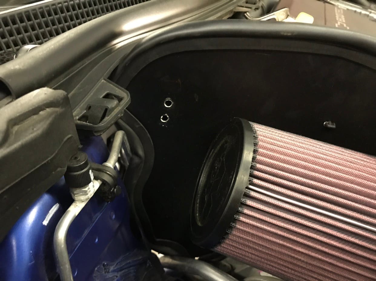
I started with using the mounting bracket for catch can as a template to mark where holes are to be drilled. I then used auto-punch for too hole, drilled a pilot hole, then drilled to a larger hole that fit the bolt I selected for mounting. I then finger tightened bolt and held catch can up to where it would be installed to triple check clearance on all sides, then pulled away catch can and marked second hole to drill, punchEd, then drilled.
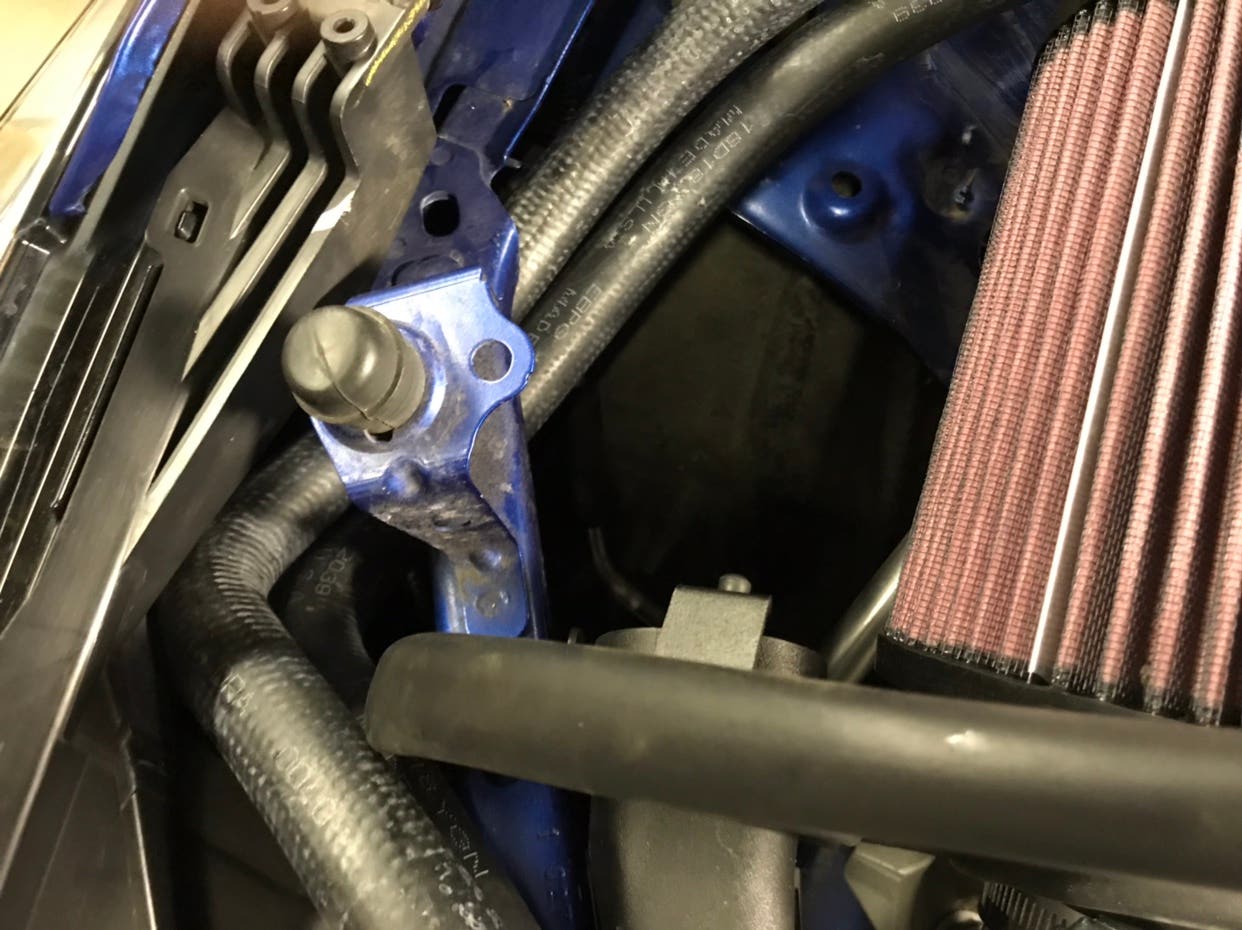
I routed the two preformed hoses I got from Napa under the headlight bracket.
![Image]()
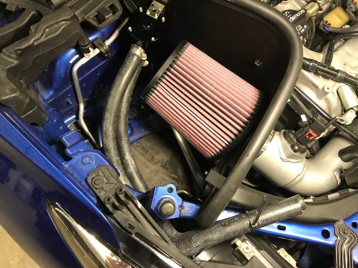
I connected to the hoses to the catch can prior to installing to the mounted bracket for ease of install. I used a hose clamp on each of these fittings. I then mounted the bracket, followed by mounting the catch can to the bracket
![Image]()
![Image]()
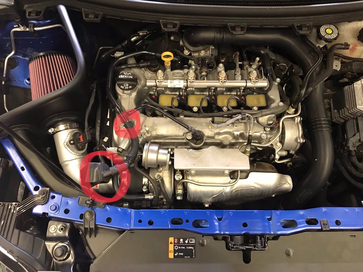
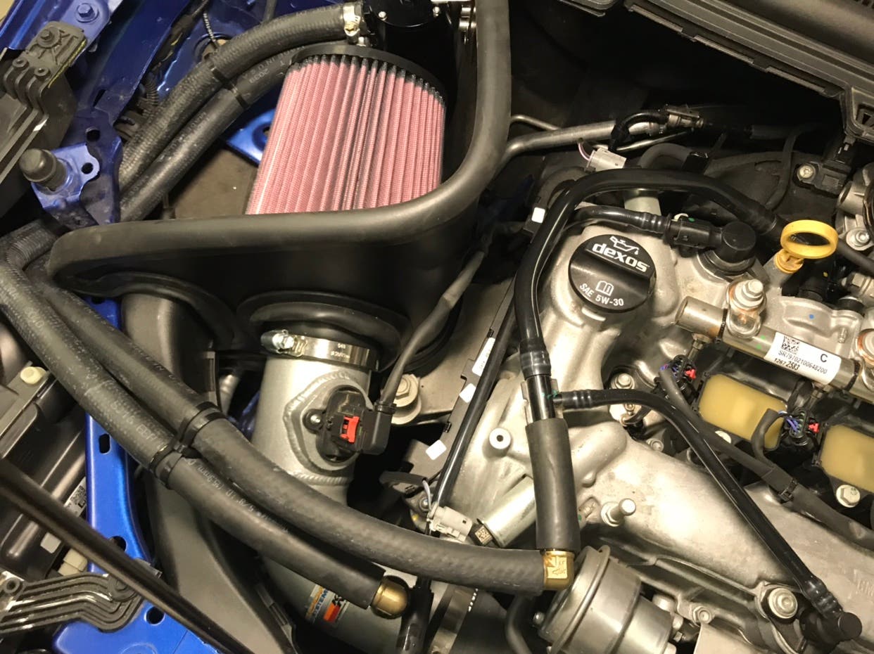
Now we are going to remove the OEM oil separator and pcv lines marked below
![Image]()
I used a razor knife to cut across the ridges on the fitting of the heat shrunken plastic tubing to remove it. Then I pulled the oil separator out of the hose leading into the intake.
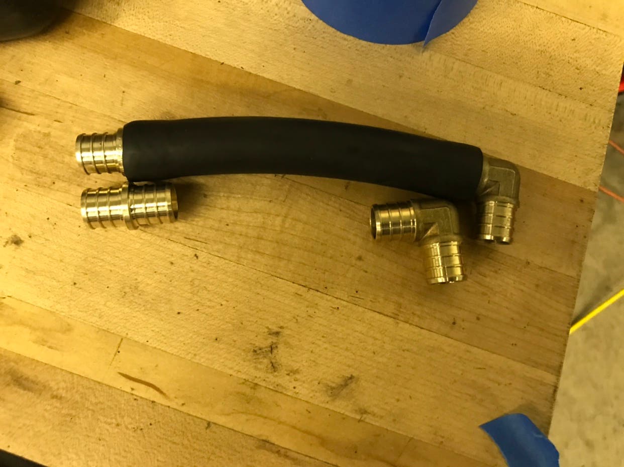
I then made the hoses that will join the two preformed hoses coming from the catch can.
![Image]()
Then I connected everything together using all the brass fittings and spare chunks of 9/16s fuel line hose.
![Image]()
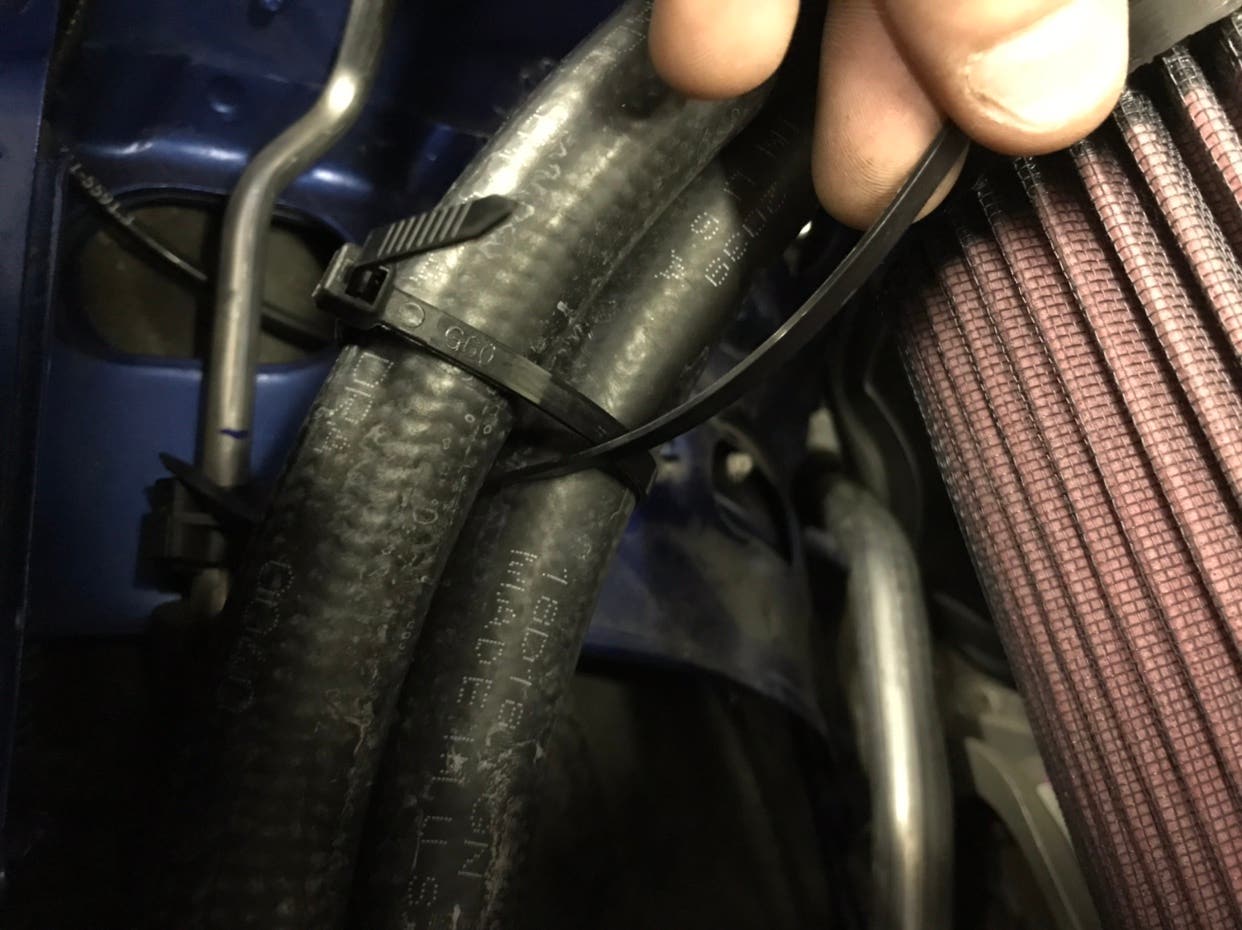
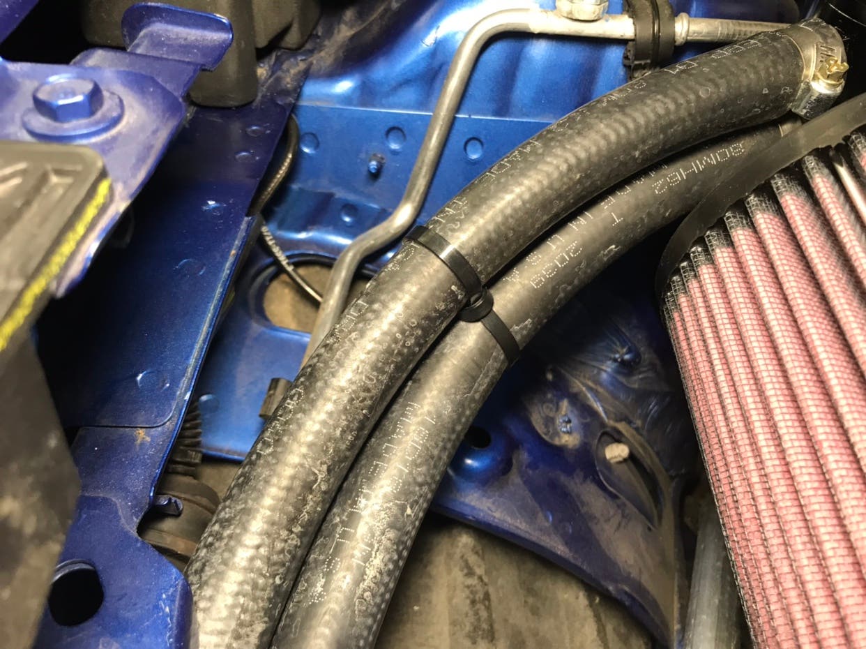
The straight brass hose connectors are under the cable ties. I also use the cable ties in a manner such that they separate the hoses by the width of a cable tie, I just think it looks nicer.
To do this you put a cable tie around both hoses you want to separate. Then you put a cable tie between the hoses and around the cable tie you just put around the hoses.
![Image]()
![Image]()
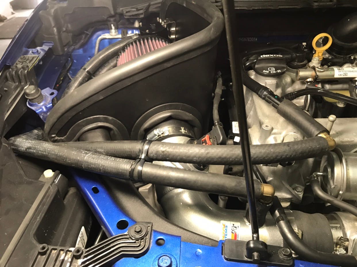
Tighten the hose clamps and the final product will look like this
![Image]()
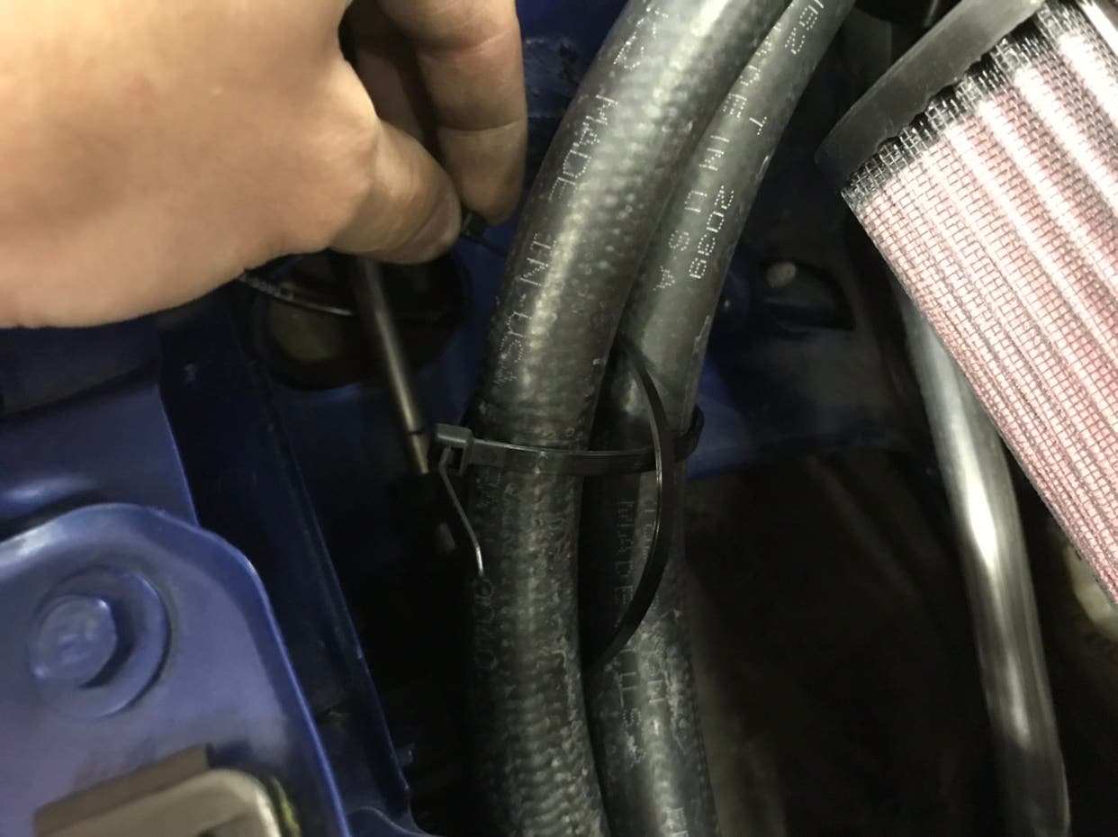
You can use more than one cable tie around the hoses for a wider coverage, which is what I did to cover the straight brass connects to make it look as if it were one continuous hose.
![Image]()
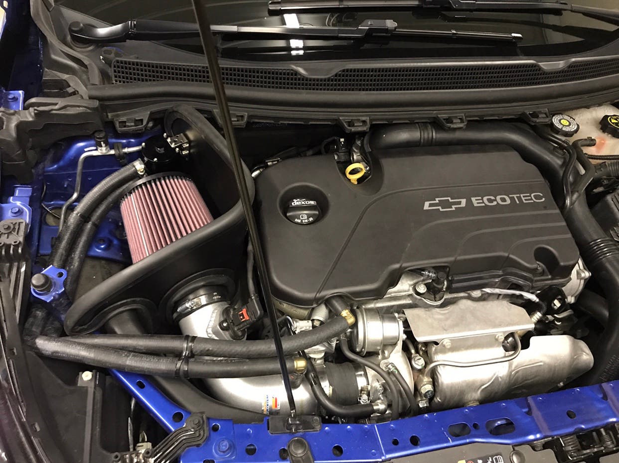
Make sure the drain on the catch can is closed, and put everything back together, you are done. Final product should look thusly
![Image]()
EXTRA NOTE, you do not need a breather on the catch can. I’d recommend not using one if you have that option, let the ventilation feed back into the intake as it is meant to.
Any questions, things I’ve missed, changes required, let me know.
Sent from my iPhone using Tapatalk
Tools required: this can be a case by case depending on where you plan on installing. You’ll need;
(2) 9/16ths brass 90 degree connectors
(2) 9/16ths straight hose connectors
(8) possible hose clamps (I used 2)
(2) 28469 hoses from Napa (what I used, they have a 90 degree)
8 inch cable ties
Hardware you select for mounting catch can
Razor knife
Torque bit to remove engine cover (think it’s a t50, don’t quote me, can’t remember)
Drill and drill bits
Permatex high performance thread sealant
Catch can-make sure the catch can had metal or brass fittings, if not, purchase some, plastic fittings are prone to failure and not where near as secure.
Pliers if you find you need them
Screwdriver for prying (if desired)
Whatever tool necessary for tightening your hose clamps.
Paint pen to match color of wherever you drill (I drilled into intake shroud, so black for me)
Instructions:
Remove engine cover using torque bit
Determine where you want to install catch can. I highly recommend getting one with a drain at the bottom, so try to find a place you can install and still have access to drain
Use the thread sealant on the plug for the top of the catch can if it has an option for a breather, and for the hose fittings. Tighten them to security.
I started with using the mounting bracket for catch can as a template to mark where holes are to be drilled. I then used auto-punch for too hole, drilled a pilot hole, then drilled to a larger hole that fit the bolt I selected for mounting. I then finger tightened bolt and held catch can up to where it would be installed to triple check clearance on all sides, then pulled away catch can and marked second hole to drill, punchEd, then drilled.
I routed the two preformed hoses I got from Napa under the headlight bracket.
I connected to the hoses to the catch can prior to installing to the mounted bracket for ease of install. I used a hose clamp on each of these fittings. I then mounted the bracket, followed by mounting the catch can to the bracket
Now we are going to remove the OEM oil separator and pcv lines marked below
I used a razor knife to cut across the ridges on the fitting of the heat shrunken plastic tubing to remove it. Then I pulled the oil separator out of the hose leading into the intake.
I then made the hoses that will join the two preformed hoses coming from the catch can.
Then I connected everything together using all the brass fittings and spare chunks of 9/16s fuel line hose.
The straight brass hose connectors are under the cable ties. I also use the cable ties in a manner such that they separate the hoses by the width of a cable tie, I just think it looks nicer.
To do this you put a cable tie around both hoses you want to separate. Then you put a cable tie between the hoses and around the cable tie you just put around the hoses.
Tighten the hose clamps and the final product will look like this
You can use more than one cable tie around the hoses for a wider coverage, which is what I did to cover the straight brass connects to make it look as if it were one continuous hose.
Make sure the drain on the catch can is closed, and put everything back together, you are done. Final product should look thusly
EXTRA NOTE, you do not need a breather on the catch can. I’d recommend not using one if you have that option, let the ventilation feed back into the intake as it is meant to.
Any questions, things I’ve missed, changes required, let me know.
Sent from my iPhone using Tapatalk


