Chevrolet Cruze Forums banner
21 - 40 of 58 Posts
The leading cause of premature failure of an ignition coil is due to a worn or bad spark plug ignition cable.
There are no coil wires on a COP system.
 
Here comes this issue again. I really thought this ECM wiring harness would be my issue. First the car started running rough and mis-firing. I changed the coil pack with new AC Delco pack. It fixed it for probably about 6 months. To be fair it was not driven everyday. Then about July 1st my wife had to drive it everyday to work. Ran fine the entire month of July. Then literally the day after my wife got her car back we started it and the coil pack melted in that 1st location as everyone else's. I thought.. oh.. bad pack. I went to GM and they warranty exchanged it. To be safe I put all new AC Delco plugs in it. Started the car and literally within 1min the new coil pack started smoking and melted in the same place. I found this discussion and thought it would be the issue. I pulled the ECM harness and I have zero continuity between pin 1 and 2... as well as zero from pin 2 to the coil one wire at the coil plug. I get good continuity at from pin one to the coil plug.

I am at a loss. I assume I can not drive it or it might literally catch fire or damage the engine since it is not firing one cylinder. The GM dealer is about 7 miles away so I guess I will have it towed to them in the morning.

Anyone on here have any updates on this issue? Are there any other known causes?
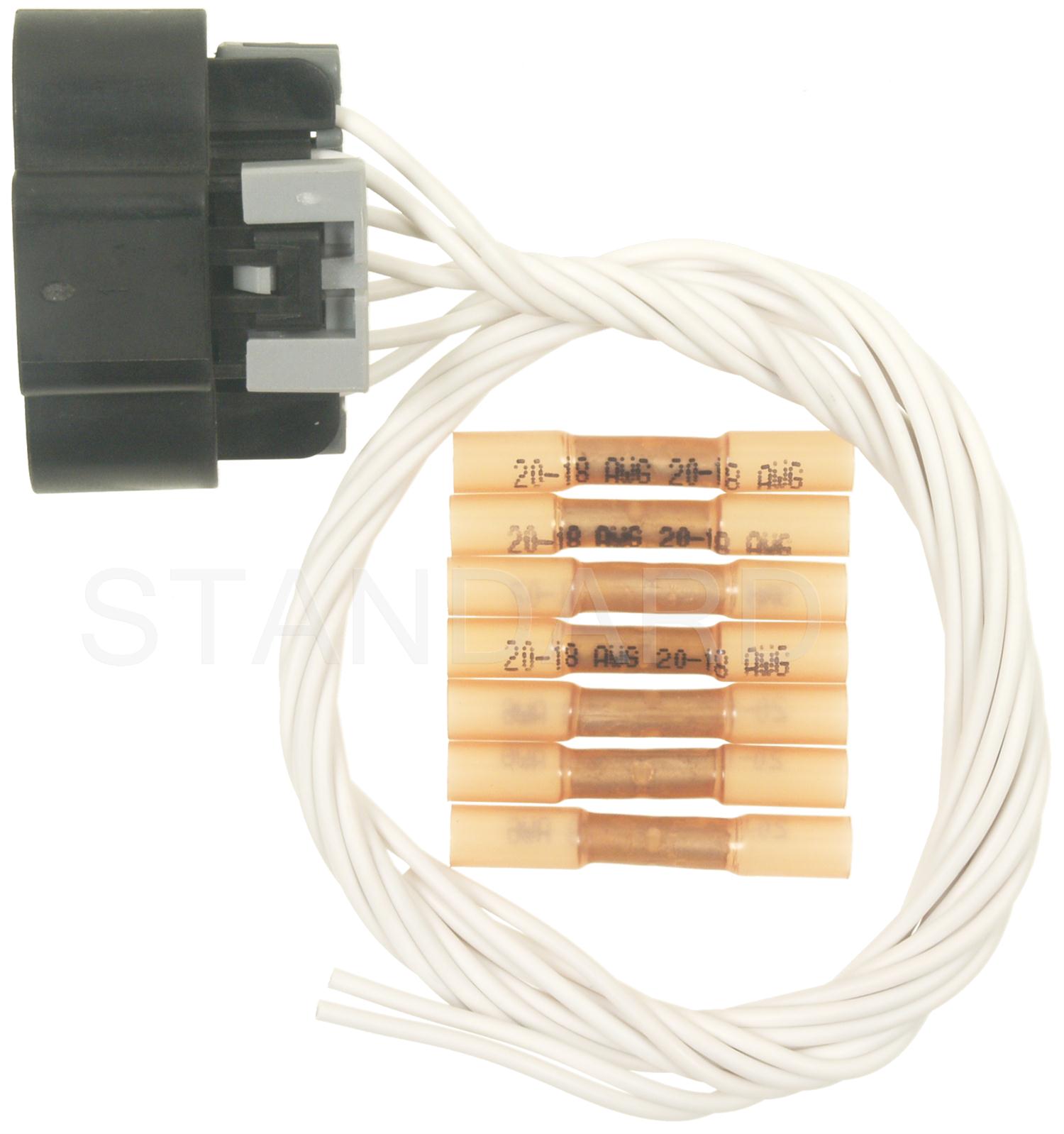
#16-NA-015: Engine Stall or Stumble - Replace Coil Connector - (Jan 21, 2016)

https://static.nhtsa.gov/odi/tsbs/2016/MC-10112283-9999.pdf


Pull the ECM connector and look for corrosion. If you have any read this:
Burning up Coil pack

or

Pull off the spark plugs boot and inspect the spring. It should have a resistor pellet integrated into. Measure the resistance of the spring from one end, to the end of the resistor pellet(looks like a tiny fuse or capsule usually). You should have somewhere between 800-1200ohms resistance. If you just have a plain spring, or if the resistance is below 800 or so, that's why you're blowing out coils. (Courtesy of Ma v e n)


And lastly:


https://static.nhtsa.gov/odi/tsbs/2016/MC-10112283-9999.pdf

Tips to ensure no misfires occur:

Remove the coil pack. If the boots are stuck on, use a small screwdriver or pick with some dielectric grease on it to go around the outside of the boot and then possibly the inside of the boot to help aid in removal.

Remember to (p)re-gap your plugs to .028, (0.24 if tuned)

Set gap with the black portion of this tool.

Image


To increase the gap size bend the ground strap up to the desired height. DO NOT LET THE GAPPING TOOL TOUCH THE IRIDIUM CENTER ELECTRODE OR PORCELAIN.

Measure the gap with feeler gauges.

Image


Throw this away.


Image


Torque to 18 ft-lbs with no anti-seize on the threads of a stock type plug.

Ensure the boots have no rips/tears or holes in them, lightly coat them with dielectric/silicone grease and make sure the resister springs are clean and not caught up in the boots when you install them.

If the plugs look bad, consider these:

-BKR8EIX-2668 (iridium plugs), ~$25, expect ~10-15k regaps on these, ~40-50k overall life.
-BKR7E-4644 (nickel/copper plugs), ~$8, expect 15-25K out of these plugs, with a regap or two required at 5-8k intervals on stock tune.

Read Hesitation Gone! for more info on the plugs.


A good replacement coil is the MSD Blaster OEM Replacement Coilpack 8236

How-To: Remove and Replace the Coil Pack and Spark Plugs.

While you are in there, if you have a cheap endoscope, look at the pistons. This can also tell you many things.
 
Had the same issue, as ChuckDaniels says it ended up being a short in the ECM plug between the coil 1 and the injector 1 wires. Its was a simple fix. Don't even have to buy a new harness or plug. The plug comes apart very easily. Simply remove the top of the plug then you can remove the piece of the plug that the pins slide into to expose the wire slots. They pull out easily from the back. Clean any corrosion on the wire ends and within the plug and apply a thin layer of dielectric grease to the outside of the wire slots, push back in and reassemble the plug.
What plug are you talking about exactly? there are 3 plugs on the ECM and I cannot seem to find a proper wiring diagram to trace these wires out. do you have any pictures of this process? from what I could see I tried to remove the top of the injector plug but ended up pulling the wires right out. I am not used to GMs method of unpinning and pinning plugs.
 
What plug are you talking about exactly? there are 3 plugs on the ECM and I cannot seem to find a proper wiring diagram to trace these wires out. do you have any pictures of this process? from what I could see I tried to remove the top of the injector plug but ended up pulling the wires right out. I am not used to GMs method of unpinning and pinning plugs.
It's the middle plug connector on the ecm.. once you pull it the
pin cover pops off the connector.. then just look for corrosion
 
Yes, I understand the ECM plastic covers. I'm wondering if he was referring to de-pinning the plugs to clean corrosion. I removed the covers and sprayed electronic cleaner didn't see any discoloring or corrosion before spraying. I'm stuck either chasing down a problem that doesn't exist, or putting in a new coil and it burning up again. Mine is cracked on cylinder 1, and sent a cloud of smoke after replacing fuse #9. I would hate to put in a new coil and waste $100+ without fixing a root cause, or at least ruling out a short in the wiring to be a problem. I'm trying to find a factory service manual or a wiring diagram but have had no luck, I'm left to removing the entire loom and hand tracing every wire.
 
I have the same problem and the same codes :(

My car started shaking and I had to replace the coil pack and the spark plugs. Then drove for two weeks nice and smooth, but suddenly again shaking. This time I put Delphi coil pack and took for a drive but the something, shaking and stopped.
Something I noticed, both coil packs got the burn on the left side as in the photo below. I do not know what else I should do? should I replace it again? should I replace the thermostat housing sensor? What are the ohm reads on the connector, please?
Auto clinics like GM dealer, Belle Tires, Midas in Michigan cost so much $labor$ and without warranty.
My car is Chevy Cruze 2015 LS
Image

Image
 
I have an update.. 3/24/2022 4pm
I replaced the Coil pack connector and coil pack. BUT THE SAME THING :(
I gave up and went to Midas, Canton MI, then they replaced the thermostat housing W sensor (TA2003DL) and throt body htr asm pipe (25192905) they charged me for only these two parts $411! .BUT, It is worth it, :) and No shaking and no burn.

Another update: 3/25/2022 6 am
I have check engine :(
 
I have my own scanner. didn't get a chance to read the codes before I tore into it. I decided to get new AC Delco Iridium spark plugs yesterday and threw those in with the proper .028 gap. after looking over the wiring some more, I found everything to be within spec. Threw the new Delphi coil pack in and prayed that it didn't pop. for good measure I pulled the coolant heater plug just to be safe. It fired right up! I'm leaning towards the coil pack which was black in color with no markings was an aftermarket one and the car didn't like that.
 
I have the same problem and the same codes :(

My car started shaking and I had to replace the coil pack and the spark plugs. Then drove for two weeks nice and smooth, but suddenly again shaking. This time I put Delphi coil pack and took for a drive but the something, shaking and stopped.
Something I noticed, both coil packs got the burn on the left side as in the photo below. I do not know what else I should do? should I replace it again? should I replace the thermostat housing sensor? What are the ohm reads on the connector, please?
Auto clinics like GM dealer, Belle Tires, Midas in Michigan cost so much $labor$ and without warranty.
My car is Chevy Cruze 2015 LS
View attachment 296700
View attachment 296699

If you plan to use an OHM meter to take these readings make sure either of the batter posts are disconnected, you do not want to put power to a meter while reading OHMs these tests are performed with NO POWER. remove your key and disconnect your negative battery terminal. The same would apply to a continuity test there should be NO POWER when performing either of these tests, you will burn up your meter and you will have a bad time diagnosing the problem.

I tore into the 2nd ECM (K20) connector from the top is where all the wiring goes from the 7 pin connector. After tracing out my wiring harness I didn't find any breaks in my wiring and it all looked to be in good shape. I do not know the exact pin out numbers on the ECM connector (K20). After de-capping this harness plug at the ECM the black holding plate on top should come off relatively easily with light pressure from the corners or ends with a pick or fine screwdriver. This will expose the pins and give easier access to test these wires, careful to not put lots of pressure on the wires otherwise they will touch together and give you false readings.

All of my wiring was rung (continuity check) end to end to determine that they were in fact the proper wires, also I checked the 7 pins in the coil pack connector (K35) against ground and power. The 7 pin connector holding it with the tab above or upright is read RIGHT to LEFT pins A-B-C-D-E-F-G.

Image


Pin A - (Red with blue stripe) is 12v power this wire should ring out to the red and blues in the ECM (K20) connector but not to ground. or Fuses 8 & 9 if this wire rings to ground there is a short in the power wires.

Pin B - (Black) is ground which goes straight to the engine block via a ring terminal right below the you can ring this to the battery negative terminal and should not ring to power pin A if you're getting a connection or ring between A and B there's a short between these two wires somewhere in the loom or in either connector. From what i've read most shorts occur in the (K20) connector

Pin C - is low reference ground which goes back to the ECM. this should read to ground but not power.

Pins D-E-F-G are all control TTL logic wires which carry 5v from the ECM to the coil to tell it when to fire a specific cylinder (1-2-3-4). these should NOT ring to Ground or Power. (pins A-B-C) or the battery (-) (+) posts. if these are ringing to power then there is 12v on a 5v circuit causing the short. the engine will still run but it will run poorly because of the constant 12v signal instead of a 5v control signal. If they're ringing to ground there's no signal going to the coil, path of least resistance.

For me I traced these 4 wires (D-E-F-G) back through the loom to the 2nd ECM connector. These are control wires and are directly connected to the ECM. I found there to be around 0.2 OHMs on all 4 of these wires

All of these were tested from the 7-pin connector (K35) and these were my readings.

A - back to the ECM connector 0.3OHMs (did not ring to ground)
B - engine block ring terminal 0.1OHMs (did not ring to power)
C - Negative battery connection 0.4OHMs (did not ring to power)
D - back to the ECM connector 0.2OHMs (did not ring to either power or ground)
E - back to the ECM connector 0.2OHMs (did not ring to either power or ground)
F - back to the ECM connector 0.2OHMs (did not ring to either power or ground)
G - back to the ECM connector 0.2OHMs (did not ring to either power or ground)


I also found another test procedure from another forum post this can be helpful to determine what's going on so ill post it again. It refers to two connectors (K35) and (K20) I noted those in my post above to help clear confusion.

Image


I hope some of this can help you.
 
New update: 3/26/2022 morning, I don't trust Midas anymore.
I have to check where is the short.
I watched YouTube in the posted above. And understood everything.
I unplugged all three ecm connectors and coil pack and coil pack connector just like above YouTube, and I followed pin D, Blue/violet, to the middle ECM connector. I successfully pulled this pin, blue/violet (pin 1) from the middle ecm connector and also pulled pin 2 of the ecm middle connector and SAW some green corrosion, so I thought this is short. So I cleaned out the corrosion by dioxide spray g5 and I test them together.. but still seeing a short (200 k ohm).
Here are some pictures
Image

Image

Image

Image

Image
 
It might be somewhere in the loom. That 7 pin connector is not stock and has been changed. You can tell from the splices and the white wiring coming off of it. I'd peel back more tape and pull off the corrugated wire protection and check further into the harness to see if there's any frayed wires.
 
If you plan to use an OHM meter to take these readings make sure either of the batter posts are disconnected, you do not want to put power to a meter while reading OHMs these tests are performed with NO POWER. remove your key and disconnect your negative battery terminal. The same would apply to a continuity test there should be NO POWER when performing either of these tests, you will burn up your meter and you will have a bad time diagnosing the problem.

I tore into the 2nd ECM (K20) connector from the top is where all the wiring goes from the 7 pin connector. After tracing out my wiring harness I didn't find any breaks in my wiring and it all looked to be in good shape. I do not know the exact pin out numbers on the ECM connector (K20). After de-capping this harness plug at the ECM the black holding plate on top should come off relatively easily with light pressure from the corners or ends with a pick or fine screwdriver. This will expose the pins and give easier access to test these wires, careful to not put lots of pressure on the wires otherwise they will touch together and give you false readings.

All of my wiring was rung (continuity check) end to end to determine that they were in fact the proper wires, also I checked the 7 pins in the coil pack connector (K35) against ground and power. The 7 pin connector holding it with the tab above or upright is read RIGHT to LEFT pins A-B-C-D-E-F-G.

View attachment 296715


Pin A - (Red with blue stripe) is 12v power this wire should ring out to the red and blues in the ECM (K20) connector but not to ground. or Fuses 8 & 9 if this wire rings to ground there is a short in the power wires.

Pin B - (Black) is ground which goes straight to the engine block via a ring terminal right below the you can ring this to the battery negative terminal and should not ring to power pin A if you're getting a connection or ring between A and B there's a short between these two wires somewhere in the loom or in either connector. From what i've read most shorts occur in the (K20) connector

Pin C - is low reference ground which goes back to the ECM. this should read to ground but not power.

Pins D-E-F-G are all control TTL logic wires which carry 5v from the ECM to the coil to tell it when to fire a specific cylinder (1-2-3-4). these should NOT ring to Ground or Power. (pins A-B-C) or the battery (-) (+) posts. if these are ringing to power then there is 12v on a 5v circuit causing the short. the engine will still run but it will run poorly because of the constant 12v signal instead of a 5v control signal. If they're ringing to ground there's no signal going to the coil, path of least resistance.

For me I traced these 4 wires (D-E-F-G) back through the loom to the 2nd ECM connector. These are control wires and are directly connected to the ECM. I found there to be around 0.2 OHMs on all 4 of these wires

All of these were tested from the 7-pin connector (K35) and these were my readings.

A - back to the ECM connector 0.3OHMs (did not ring to ground)
B - engine block ring terminal 0.1OHMs (did not ring to power)
C - Negative battery connection 0.4OHMs (did not ring to power)
D - back to the ECM connector 0.2OHMs (did not ring to either power or ground)
E - back to the ECM connector 0.2OHMs (did not ring to either power or ground)
F - back to the ECM connector 0.2OHMs (did not ring to either power or ground)
G - back to the ECM connector 0.2OHMs (did not ring to either power or ground)


I also found another test procedure from another forum post this can be helpful to determine what's going on so ill post it again. It refers to two connectors (K35) and (K20) I noted those in my post above to help clear confusion.

View attachment 296716

I hope some of this can help you.
Thank you, I really needed these readings. I have to continue tomorrow morning.
By the way, I did this test today:
  1. Unplugged all the connectors (the 3 ECM connectors, and the coil-pack connector) and the coil-pack.
  2. Read between pin1 (Ign coil1) & pin2( fuel injector wire circuit 1) on K20 for continuty and found it is 200 kohm.
  3. I pulled these two pins out from the K20, confirmed not teaching, but still reading the 200 kohm.
  4. Do not you think it must be no connection between these two pins of K20?
Appreciate the answer.
 
The 12v power (pin A on the 7 pin connector) is apart of the fuel injector circuit it's connected by a red wire with a blue stripe. If you open the harness up, a bigger gauge wire goes from the K20 connector to a factory splice. This splice has multiple 16-gauge wires off of it which feeds power to each injector and other devices. I didn't trace them all so I don't know exactly what it all feeds.
 
The 12v power (pin A on the 7 pin connector) is apart of the fuel injector circuit it's connected by a red wire with a blue stripe. If you open the harness up, a bigger gauge wire goes from the K20 connector to a factory splice. This splice has multiple 16-gauge wires off of it which feeds power to each injector and other devices. I didn't trace them all so I don't know exactly what it all feeds.
Thank you for the reply. I have to order Caig Deoxit Gold G5 from Amazon. pray it to the connectors to eliminate the corrosion. Did you do that?
 
21 - 40 of 58 Posts